
Propeller induced velocity: what the blade really sees
Induced velocity is the change of velocity that the propeller itself gives to the fluid, upstream as well as downstream of its blades. It has two components, one along the axis and one in the direction of rotation. Since it changes the angle at which the fluid reaches each section, the calculation of blade twist must take it into account. You do not need to master this notion to use Heliciel, but it helps to understand what the software computes.
On this page:
- Where induced velocity comes from
- Two situations to see it
- What the blade section really sees
- A calculation that loops on itself
- Tangential induction and section camber
This page gives a first approach; the detailed formulas are in the propeller calculation theories.
1: Where induced velocity comes from
When the fluid passes through the propeller, the blade sections deflect its path. This is action and reaction: the thrust the fluid exerts on the propeller, the propeller exerts on the fluid; the torque the fluid exerts on the blade, the blade exerts on the fluid. The fluid therefore changes speed and direction. Two components are distinguished:
- axial induction, along the rotation axis, written Wa;
- tangential induction, in the plane of rotation, written Wt.
They are often expressed as dimensionless induction factors: the axial factor a applies to the fluid speed V, the tangential factor a' to the rotational speed Ω r. They give the axial induced velocity (a × V) and the tangential induced velocity (a' × Ω r).
2: Two situations to see it
- An aircraft standing on the runway, engine running. Far ahead of the propeller, the air is still. Yet just in front of the blades, a very real airflow is drawn into the propeller, strong enough to be dangerous to anyone nearby. This airflow is induced by the propeller: it accelerates the fluid and drags it in its direction of rotation.
- A wind turbine. The air arriving in front of the rotor is slowed down. The rotor acts as a more or less "porous" plug, which the wind partly flows around. This is where the Betz limit comes from: a wind turbine cannot capture more than 16/27, or 59.3 %, of the energy of the wind crossing its disc. The wake, for its part, rotates opposite to the rotor.
If the velocity seen by the blades of the standing aircraft were computed from the rotational speed and the far-upstream air speed alone, no axial component would be found. The section would then work at a wrong angle of attack: that is why blade twist is computed with the induced velocities.
3: What the blade section really sees
Induction is felt downstream of the propeller, but also upstream: the section acts on the fluid even before touching it. At the propeller plane, the axial induced velocity is half that of the far wake. The velocity really seen by the section therefore differs from the apparent velocity computed without induction:
| Axial component | Tangential component | |
| Propulsive propeller | V × (1 + a): the fluid is accelerated | Ω r × (1 − a'): the fluid turns with the blade |
| Wind or tidal turbine | V × (1 − a): the fluid is slowed down | Ω r × (1 + a'): the fluid turns opposite to the blade |
The two diagrams below place these velocities on a section: Wa and Wt are the axial and tangential induced velocities, W their resultant. Vr is the relative velocity computed without induction, Ve the effective velocity the section sees once W is added. β is the pitch angle and α the angle of attack.

Propeller in wind turbine mode: velocities, angles and forces on a section.
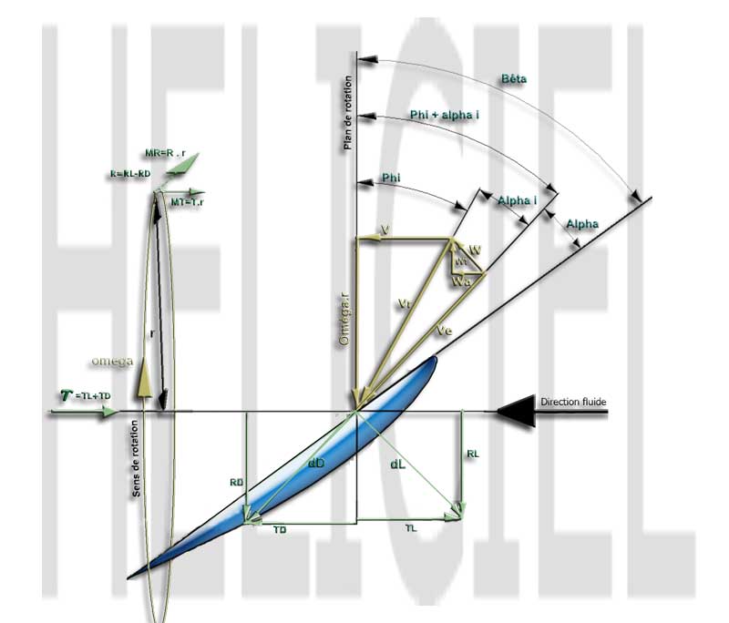
Propulsive propeller: velocities, angles and forces on a section.
4: A calculation that loops on itself
The difficulty is that everything depends on everything. Induction is caused by the lift and drag of the sections; but lift and drag depend on the angle of attack, which induction changes. The equations of the forces on the sections and those of the momentum of the fluid must therefore be solved together, for a given upstream speed and rotational speed.
Heliciel evaluates induction with the blade element momentum method (BEM, Blade Element Momentum), including tip losses. For each element, it iterates (Newton's method) until the equations converge.
5: Tangential induction and section camber
Tangential induction also affects the shape of the section. It grows across the blade, from leading edge to trailing edge, then doubles in the wake: the path of the fluid curves as it crosses the blade. This curvature changes the camber of the section as seen by the fluid. To keep its theoretical camber, the real section must therefore be deformed to follow this curved path.

Root of an axial fan blade: velocity triangles, path curved by tangential induction, nominal section (left) and corrected section (right).
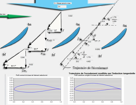
The same correction at the root of a tidal turbine blade.
Heliciel computes the induced velocities of each blade element and uses them to set the optimum twist. A camber correction tool also applies the deformation due to tangential induction to the 3D model and to the exported 3D files used to build the prototype.
To go further, we can see how these velocities enter the propeller calculation theories, or come back to apparent velocity and angle.
 Global site map
 Mecaflux
 Tutorials Mecaflux Pro3D
 Tutorials Heliciel
 Tutorials Heliciel PRO CFD
 Mecaflux Store
 Compare software functions
 Quotes, Orders, Payment Methods
 project technical studies